Home
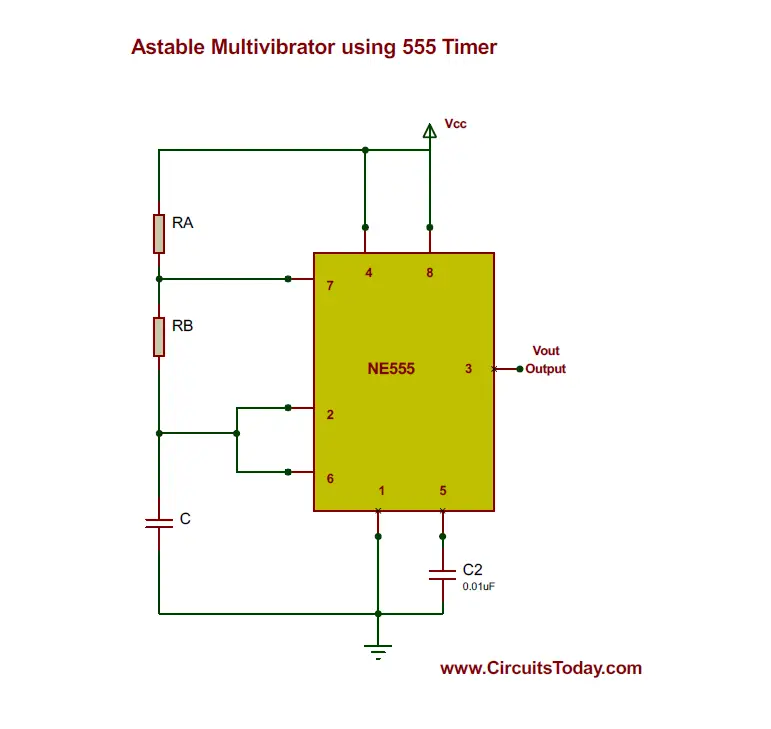
/ 555 Timer Schematic Symbol : Schematic Circuit Diagram Astable Multivibrator Using 555 Timer Proteus Simulation : Although a circuit common symbol is shown, the collector is not.
555 Timer Schematic Symbol : Schematic Circuit Diagram Astable Multivibrator Using 555 Timer Proteus Simulation : Although a circuit common symbol is shown, the collector is not.
555 Timer Schematic Symbol : Schematic Circuit Diagram Astable Multivibrator Using 555 Timer Proteus Simulation : Although a circuit common symbol is shown, the collector is not.. The schematic shows (3) circuits, because one circuit does not work well over the entire vcc range. The 555 timer is a simple integrated circuit that can be used to make many different electronic circuits. Only attach an 1k resistor + led from pin 3 to ground. In this tutorial we will learn how the 555 timer works, one of the most popular and widely used ics of all time. When vcc > 9v, the base to emitter junction starts to zener and.
The threshold voltage for the first ic 555, which is determined by the. 5.29 shows a 555 timer configured as an astable or multistable multivibrator 66. The output of uc (upper comparator) which is reset input to rs. The diagram below the 555 die photo and schematic below are interactive. Monostable mode is great for creating time.
How Many Different Configurations For 555 If Only Need Use Pwm General Electronics Arduino Forum from blog.customsiliconsolutions.com Introduced in 1971 by the american company signetics, the 555 is. Usually used to create time delays. Instead, use a lower value capacitor and a higher value resistor. Only attach an 1k resistor + led from pin 3 to ground. Click on a component in the die or. When the 555 output (pin 3) is low the discharge pin is connected to 0v internally. Although a circuit common symbol is shown, the collector is not. So far i have tried drawing from this link which was supposed to produce.
When vcc > 9v, the base to emitter junction starts to zener and.
The 555 timer is a simple integrated circuit that can be used to make many different electronic circuits. The 555 timer is a commonly used ic designed to produce a variety of output waveforms with the the 555 timers name comes from the fact that there are three 5kω resistors connected together if not, schematic wrong, or 555 defective. The versatile 555 timer ic can be used in a variety of circuits like time delays, oscillation, pulse generation, pulse width modulation etc. (1) for all available packages, see the orderable addendum at the end of the datasheet. The basic 555 timer ic included in the chipkit™ starter kit is the ne555. When vcc > 9v, the base to emitter junction starts to zener and. The 555 timer ic is an integrated circuit (chip) used in a variety of timer, delay, pulse generation, and oscillator applications. The diagram below the 555 die photo and schematic below are interactive. The 555 timer ic is an integral part of electronics projects. In a schematic, the 555 symbol will look similar to this 5.29 shows a 555 timer configured as an astable or multistable multivibrator 66. This circuit generates a stable train of pulses. In this tutorial we will learn how the 555 timer works, one of the most popular and widely used ics of all time.
The 555 timer ic is an integrated circuit (chip) used in a variety of timer, delay, pulse generation, and oscillator applications. Look at the circuit diagram. Instead, use a lower value capacitor and a higher value resistor. This circuit generates a stable train of pulses. The 555 timer was introduced over 40 years ago.
The 555 timer is one of the most widely used integrated circuits in electronics projects.
The 555 timer changes its output depending on the state of two inputs. Click on a component in the die or. Derivatives provide two (556) or four (558) timing circuits in one package. Its function is to discharge the timing capacitor in astable and monostable circuits. This tutorial provides sample circuits to set up a 555 timer in monostable, astable, and bistable modes as well as an in depth by wiring the 555 timer with resistors and capacitors in various ways, you can get it to operate in three different modes: This article covers every basic aspect of 555 timer ic. The diagram below the 555 die photo and schematic below are interactive. It's a simple source of oscillating current that can power blinking leds, generate tones, and lots of other useful applications. The 555 timer is a simple integrated circuit that can be used to make many different electronic circuits. For standard 555 timers use timing resistor values between 1k ohms and 1m. From wikipedia, the free encyclopedia. Instead, use a lower value capacitor and a higher value resistor. The 555 timer ic is an integrated circuit (chip) used in a variety of timer, pulse generation, and oscillator applications.
Look at the circuit diagram. So far i have tried drawing from this link which was supposed to produce. Due to its relative simplicity, ease of use and low cost it has been used in literally thousands of applications. If you still need a detailed understanding of the 555 timer. From wikipedia, the free encyclopedia.
1 Minute 5 Minute 10 Minute And 15 Minute Timer Circuit Diagram Using Ic 555 from circuitdigest.com Due to its relative simplicity, ease of use and low cost it has been used in literally thousands of applications. The rs latch in the 555 timer can be used with the reset and trigger inputs. The 555 timer is an integrated circuit, it is extremely versatile and can be used to build lots of different circuits. The output of uc (upper comparator) which is reset input to rs. How do i draw this schematic on latex? From wikipedia, the free encyclopedia. Introduced in 1971 by the american company signetics, the 555 is. Above schematic diagram shows the 555 timer monostable multivibrator circuit.
Due to its relative simplicity, ease of use and low cost it has been used in literally thousands of applications 555 timer schematic. The rs latch in the 555 timer can be used with the reset and trigger inputs.